Sunday, January 31, 2010

Research and Inspiration


For some, doing the hard yards researching stuff is boring. Spending time looking for information that could be better spent actually doing some modeling is just not some peoples idea of a good time. Not me though. I’ve got a real love for researching things I’m interested in, and can in all honesty spend far too much time doing so once I get started.

With the spare room layout, after making the decision to go with the code 55 rail to give it that real branch line look, I’ve been spending some time looking for as many photo’s of branch line track as I can find.

Looking through web sites which contain photo libraries like the New South Wales State Library http://acms.sl.nsw.gov.au can uncover a plethora of absolutely brilliant information. I usually start by using simple word searches to being with like NSWGR, railway, locomotive etc, as these will typically narrow down the subject matter. From there I sometimes find photo collections which mentions the area of the photo which then gives another key to finding more information.

Whilst searching over the past few days I came across the photo of Darnick which I’ve added to this post, and whilst it is a simple photo of a single line running through an almost desolate are with nothing more than a few houses and a gangers shed, the more I looked at it the more it interested me.

Each house is different and is flanked by a different fence, the sleepers are covered in the centre of the track but very little is evident on the outside track edges with the sleepers almost completely exposed, the gangers shed with the sleepers laid out neatly in front of the shed, between the rails and on the far side, 44 gallon drums, the trike, the water tanks, telegraph poles, and even the slight undulation and lay of the land which is not as flat as it first appears with a subtle drainage ditch running alongside the shed and towards the water tanks, and the telegraph poles appearing to have raised ground running either side of them.

For a person with not a lot of space, you could actually spend a lot of time and effort trying to accurately replicate a scene like this as a diorama, or even as a mini scene between two more major features on the layout, and I think it would be as interesting as a multi track main line with stuff crammed in everywhere.

Whilst I can’t see place on my layout for this scene, there are elements within it that could easily be used on almost any layout featuring a branch line feel, and plenty that can be learnt about the way items can be placed around a railway line.

The other area of research I’ve been doing has been in relation to track dimensions especially concerning points with the gauge and flangeway sizes. I’ve looked into the OO-SF standard which closes the gauge up from the std 16.5mm to a narrower 16.2mm, and then setting the flangeways at a narrow 1.0mm giving a much closer to prototype look. But amongst reading lots and lots and lots of information about these dimensions, there was some questions about the effect it may have on the check gauge and I got the feeling that it may not be the most foolproof of dimensions.

Another local modeler of some note, Terry Flynn, has been advocation a set of finer scale dimensions for points which are not too far away from the OO-SF dimensions, but after carefully examining them, appear to be a lot more robust and will suit the mixture of RP25/110 and RP25/88 wheels used on the various bits of rilling stock I own.

Part of the reason for the research onto these dimensions is that I’d like to get some roller gauges made to help with building track and points, and ideally if they are something that others could use, a bigger batch could be ordered cutting costs per unit. At the moment I’ve put some feelers out to get an idea on costs per unit or per batch of units, but it’s a slow process it seems, and I’ll be sure to post up any information I get as it comes to hand.

Apart from the research, progress has been slow on actual modeling, and with a relative coming to stay for a week, the spare room has been turned back into a guest room, modeling desk cleaned up enough drop the extension and close the doors to make it all look neat and tidy. Makes it hard to do anything, but that is the compromise I made when subtly trying to turn another area of the house into manland.
Sunday, January 17, 2010

Necessity is the Mother of Invention


One of the things I like about this hobby, is that it gives the mind a workout at times. I like a challenge, a chance to solve a problem, and when it involves designing and making something of use, that's even better.

With the spare room shelf layout, I've made a decision to hand lay not only the points, but also the track. It was a conversation on a forum about the actual size of sleepers and their spacing on both the NSWGR and Victorian railways and the comparative sizes of Peco, Micro Engineering and Tilig flex track.

I was going to use Peco code 75 which has a nice fine look to it, and probably has the best sleeper spacing to suit NSWGR track, however being essentially a branch line layout, the sleeper spacing would be a little wider than the Peco track. I could snip the spacers between the sleepers and space them out, but that would be rather fiddly.

Another thing that has made up my mind to hand lay is that it gives me the opportunity to use some code 55 rail, which really does look good to my eyes and suits the branch line track work. As a teenager (16yo or so) I attended a modelling convention, possibly at Revesby circa 1986?, and in attendance was a diorama style layout module, Wombat Floor Mills by James McInerney, http://www.cia.com.au/bullack/BL18.jpg.

The track was all hand laid code 55, beautifully detailed with point rodding and light ballasting, and I was very very impressed. It certainly looked a treat compared to my code 100 track of the time, and I remember thinking to myself how nice it would be to have the money and time to have track work like that. Of course the money isn't so much in the track, but in what was basically the need to have expensive brass engines with fine flanges to run on it. James has a web site with lots of info on this fine layout here http://www.cia.com.au/bullack/

More recently, a fellow blogger http://superfreighter.blogspot.com/ has been producing some exceptional looking NSWGR based track and points for his own layout. This is is a classic example of the branch line look that I would like to capture, with the very fine rail and slightly wonky sleeper placement that just oozes old world character.

So with this new aim in sight, the one thing I will need apart from some lengths of rail and some strips of PCB, is a LOT of wooden sleepers. With the branch line maximum sleeper spacing of 2' 10-5/8" (two foot, ten and five eighths of an inch) or 879.45mm working out to around 10mm in HO scale, simple maths says I need around one hundred sleepers per metre. I'm guessing there will be somewhere in the region of twenty five to thirty metres of track to lay, so something like two thousand five hundred to three thousand sleepers will need to be cut!

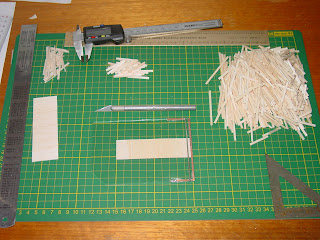
Measuring and cutting this amount of sleepers sounds like a very tedious job indeed if each one has to be measured and cut separately. There has to be a way of making the process simpler and faster. So with a look around the desk, and a bit of thought into it I've come up with a jig for churning out sleepers at a reasonable rate with a minimum of fuss.

I found a small pieces of glass measuring about 13.5 x 9cm, and simply superglued three pieces of PCB to it, two short lengths on each side and a long length across one end. I left a gap between the side and end piece of PCB on one side slightly bigger than a sleeper width.

I then soldered a piece of code 75 rail on top of the side strips a sleeper width back from the end strip. Now all I have to do is cut a single strip of balsa to the width of the sleepers I need to cut, feed the strip under the rail until it is against the rear strip, and using the rail as a guide slice through the balsa with a sharp craft knife cutting the sleeper to width in the process. I can then quickly push it out through the gap between the PCB and then slice the next sleeper to width in a fluid motion.

I found that I can actually cut two sleeper widths of balsa and cut it almost all the way through, so I can cut two sleepers at the same time and simply snap them apart after cutting. I've tried to take a video with my digital camera of cutting a single width bunch of sleepers to illustrate this technique. I'f I'd thought ahead and made the jig a little wider I could cut three widths in

I managed to get over 1,000 sleepers out of a sheet of 100x915mm balsa over about an hour and a half or so which wasn't too bad really. It was certainly worth taking the ten minutes or so to make a simple jig which allowed me to churn out the sleepers at such a rate.

Painting them may take a little longer however and I am thinking about ways to handle this. I'm sure like most other things there are almost as many ways to do it as there are people doing it, and like always any suggestions are gratefully accepted.

Sunday, January 10, 2010

Fast Moving Projects


The shelf above my new desk has been dubbed the "Fast Moving Projects" shelf. This is where projects are to be placed that are being worked on, as opposed to those one sitting in drawers awaiting being began. The idea is that I can only fit so much on that shelf, so I have to finish off something on there before I can start something else. This way hopefully things will get finished and not too many projects will be on the go at any one time.

The past few day have seen the bending up of some fine wire handrails for the GHG brake van I started about a year ago, some soldering on a set of points, and doing some experimenting with using PVA white wood glue to make flush glazed windows, but more on that another time.

Back in September last year I wrote about wanting to build the one off Dairy Farmers bogie Milk Tanker, BMT1. http://gunnedahandbeyond.blogspot.com/2009/09/where-does-time-go.html

Well today saw the first steps towards making it actually happen. I had already bought a NSWGR E Flat Wagon kit, which made up the basis of BMT1. Today saw the slow process of replacing the mounded plastic truss rods with fine wire ones. I tossed up not bothering going to this level of detail, but after looking at the moulded ones for a while I decided that I'd regret it if I didn't give it a shot. So the rod sections were cut from the bits that mount them to the wagon floor, and then those mounting pieces had to have very small holes drilled into them to accept the wire. Not a difficult job, but very fiddly. Next the wire needed to be bent up to the correct profile and length, so once the first one was made and to the correct dimensions, I made a simple little jig so the others could be bent to the same shape and then trimmed to length as the were test fitted. It was nothing more than an off cut of pine and three thumb tacks bit it worked a treat. If you are ever doing something that will require a degree of repetition, I cannot recommend making a jig enough.

So far, only the truss rods are done, the brake cylinder and air tank are fitted underneath and the head stocks are in place, but even sitting on the bogies it is starting to take shape. Pictures is the wagon in front of a picture of BMT1.

Observant people may notice that BMT1 appears to have a slightly different position for the air tank (?) and I'm not sure if I can make out a brake cylinder. However this first one is very much an exercise in trying a few different techniques out rather than shooting for a prize winning version first go so I'm not going to go overboard worry about every single little detail. Besides, I don't have any real good images or plans of the real thing so it's very much making it "look" right.

I bought some PVC tubing from Bunnings which will make up the twin tanks. The diameter of the tanks works out to 23.6mm in HO. In buying the PVC tubing however, I must have fallen into a bit of a trap for young players. A few weeks ago I bought some PVC tubing that was advertised as being 25mm. It looked a bit large to me but anyway I grabbed it and put it away until Yesterday when I pulled it out and it measured 33.7mm o.d. and 30.1mm i.d., so I'm not too sure where they get 25mm from???

So this morning another trip to Bunnings to buy the right sized PVC tubing. Once again I picked up the 25 mm tubing which looked too big, but being a bit smarter this time took it to the tool section and measured it with a ruler. Sure enough, 33.7mm. Measuring the 20mm o.do PVC tubing nets a measurement of 26.6mm o.d.

With the real diameter of the tanks working out to 23.6mm in HO, I may have a look at cutting a longitudinal section out of the tubing and then squeeze it back together and glue it to get it down to close to the right size. I guess about 9.4mm will need to be removed to bring the overall diameter down to the required size. Can you m.e.k. PVC tubing???

As an aside, you can also buy 25mm electrical conduit in four metre lengths for about $5 instead of about $2.50 per metre for the plumbing PVC. Had I been able to fit it in the car I may have gone that way, although how many tankers am I going to build?

As nice as it is getting some of these projects done I do need to get back into the shelf layout and hope to get a module underway with some tracks and points down soon.