February 26th was the previous update, so just under four months ago,
time certainly seems to be flying by at a rate of knots this year that’s for
sure. In my last post I mentioned that it had gotten quite difficult getting
down to the train shed due to no longer being able to walk more than a few
steps. Unfortunately even standing is no longer possible, however, whilst I am
now permanently in a wheelchair, it is on the positive side a rather fancy
electric one which I can control with my chin, and I can now quite easily get
around the house, and more importantly down to the train shed so that work can
continue on the layout, and continued it has.
I was again fortunate and very appreciative that my mate (who was
responsible for most of the layout construction) was able to spend a couple of
days up here continuing on the work done in February. At that point all of the
points and about 80% of the track was permanently down, and about 60% of the
wiring underneath was basically in place across the three modules.
The first job was to complete where track goes across module joins, a
job my mate was not looking forward too as he doesn’t find the process of laying
track in anyway therapeutic, relaxing, or even mildly enjoyable! However, the
laying of the somewhat fiddly sections of track was completed quite
successfully, and whilst I had full confidence that they would work fine, he
had a rather large look of relief and amazement when a Trainorama BWH was
pushed across each module join without any signs of derailment.
With this relatively small (in overall terms) amount of track work
completed, that lone BWH was now able to be “5 finger shunted” from the corner
module that leads into Gunnedah Yard, across the module join and through the
centre module which contains most of the main yard, and then across the next
module join to the corner module on the far side of Gunnedah Yard.
With track work out of the way for now, it was time to remove the centre
module from the layout, and place it upside down on the mobile tool cabinet/workbench
in the centre of the room. Once again the modular construction just makes
working on each section of the layout so much easier, and having just about all
of the tools and wiring supplies in the cabinet puts everything within easy
reach.
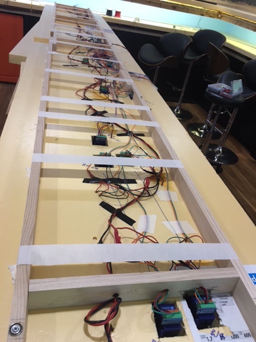
There are I think fifteen sets of points on the centre module, and the
yard track is between three and five roads along its approximate three and a
half meter length, so there is a sizeable amount of wiring underneath this
module once you take into account droppers of each section of track and points
needing to be joined to the main bus wiring running the length of the module,
and each point motor having five wires to be connected for both frog polarity
switching and actual point blade switching.
This module was approximately 40% wired, so there was still a
semi-substantial amount to be completed, but due to my mates ability to get up
to speed on these things very quickly (taking into account the wiring already
there was started by somebody else), and also due to my meticulous (if I do say
so myself) note keeping and having everything in relation to wiring clearly
written out, the soldering of droppers to the main bus and routing to the point
motors, and then attaching and running the pairs of wires for the point
activation was completed.
At this point all of the wiring was given a visual once over to make
sure that everything looked okay, or at least nothing was obviously wrong (like
a red wire attached to a black wire), and it was time to place the module back
into position on the layout. The main bus wiring on each module has a plug, so
that once in place it quickly and easily connects to the main bus wiring
running around the room. Once connected it was time to switch on the DCC system
and see what happened.
Assuming that the mass of wiring had all been connected properly
absolutely nothing should happen, an incorrect connection causing a short
should see the light bulb glowing brightly, and we joked that even worse we
could see smoke or even fire, but to his surprise and my (to be perfectly
honest) expectation, absolutely nothing happened, which meant that either
everything was perfectly connected, or nothing was actually powered. Grabbing a
small single offcut of rail and placing it across a section of track saw the
orange light bulb glowing brightly, indicating that the module was indeed
powered and the short circuit identification was working as it should.
The next step was to take every set of paired wires from each point
motor, and attach them to the “Alpha Switch A” boards which have been
temporarily hung in place for testing purposes.
These boards which are from DCC Concepts in Western Australia make for extremely
easy switching of points, a pair of wires from each point motor goes to a set
of screw terminals on the board (each board has six sets of terminals), and on
the opposite side of the board are a pair of socket’s that the LED pushbutton
switches are plugged into.
The great thing about this system is that each of the six outputs can
drive two point motors, so where you have two sets of points that will always
be switched together, you can switch both sets of points with the press of one
LED pushbutton switch.
There is an even better feature with these boards, and that is the
ability to use a three LED pushbutton switch system, which is perfect for
showing route selection where you have a pair of points in a crossover
situation, so you have a green LED for each straight route selection, and a
single LED indicating the crossover route. To switch the points from the
straight ahead position you press the single LED pushbutton in the crossover
position on the track diagram, and both sets of points will switch, to return
them both to the straight ahead position, you only need to press one of the LED
pushbutton switches on either of the straight routes, both sets of points will
be activated, and BOTH LED pushbutton switches on the straight routes will
light up.
So it is a matter of drawing the track plan onto a panel and mounting
the LED pushbutton switches in the appropriate positions, and you end up with
pushbutton point switching with LED route indication as well. I have added a picture
of a sample control panel, and a diagram of how the LED pushbuttons are
connected when three are used to switch two pairs of points in a crossover
situation.
Once all of the wires from the point motors were connected to the boards,
three boards are needed to switch all of the points for the main Gunnedah yard
section, all of the LED pushbutton switches connected, and the boards were
connected to the three wire power bus also running around the room, it was time
to switch on the power supply for the point motors and see what happened. The
power supply is also from DCC Concepts and is specifically designed to go with
the boards, which just makes life very easy.
With the power supply turned on, half of the LED pushbutton switches
immediately illuminated, and about twenty-one sets of point motors whirred into
life, this was a very good sign. It was then just a matter of individually
testing each set of points, and whilst there was a slightly scary moment when a
single set of points did not want to work, it was a relatively simple matter of
lifting the module at the front and have a peek underneath, where thankfully it
was nothing more sinister than a pair of wires pushed into the wrong terminals
on the point of motor, and once corrected the point motor activated as it
should.
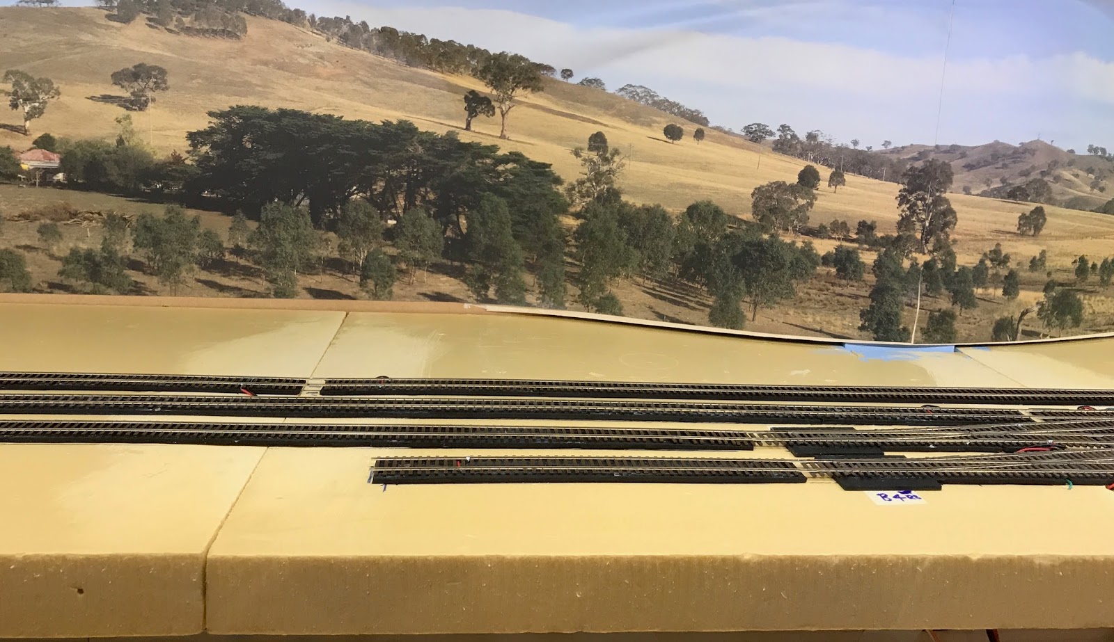
At this point we had both track power and point activation power, so it
was time to place a 48-class on the track on the corner module leading into
Gunnedah Yard, and set is on its way through the yard. It went quite happily
across the first module join and continued through the yard until it stopped
and the orange light bulb illuminated brightly, bugger! At first I thought
maybe the frog had been wired to the wrong terminal on the point motor, but it
was actually nothing more than running the engine against the points that were
set the wrong way, so again the wiring was all done correctly, and the
short-circuit indication worked as it should.
About fifteen minutes was spent running the 48-class back and forth from
one end of the yard to the other, switching routes each time, and apart from
one or two slight stutters in one spot (probably no more than dirty track)
there were no derailments or shorts, which I thought was bloody fantastic.
Getting to this point where all of the points and about 95% of the track
is permanently laid and operational for the main Gunnedah Yard section, which is
a run of around eight metres of connected track end to end, represents a
massive amount of work by friends and family, giving up their time so that I
can see my goal of building a representation of Gunnedah come to fruition. This
is something that I certainly can never adequately repay, but nonetheless am
massively appreciative of.
The next phase of construction will concentrate on constructing a simple
lift in section which will go across the doorway, and with some track
temporarily laid around the rest of the room, trains will be able to be run
continually around the room, so whilst the operating of Gunnedah Yard will be
left to visitors (of which I hope there will be a few), it will be nice to just
sit in the middle of the room and watch a couple of trains meander around.
Cheers for now
Darren


2 comments:
A great mile stone for you and your friends and family to see the enjoyment we get out of the hobby. Malcolm from Wangaratta.
Darren
You are an inspiration! The support of your friends and family is amazing as well. I have seen very few layouts that have been built so well, it is a credit to you and the support from family and friends shows how much you are appreciated in their lives.
Well done.
Ray P
Post a Comment